Case History
1. Product History
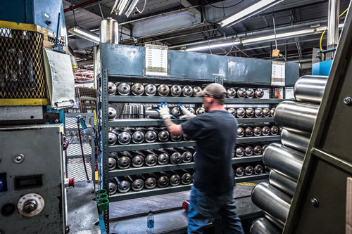 Larson Tool & Stamping started producing D.O.T.-certified pressure cylinders in the mid-1960s. At that time, we were manufacturing cylinders for use as disposable refrigerant containers and dry chemical fire extinguishers. Larson’s investment in the pressure cylinder market was substantial and included complete mechanical deep draw press lines, custom-made assembly equipment, and a 26” X 26” roller hearth electric furnace for copper brazing the assembled shells.
In 1971, a major fire extinguisher manufacturer contracted Larson to produce a 10-pound capacity dry chemical fire extinguisher cylinder. This cylinder was an adaptation of one of the refrigerant containers then being produced and consisted of a two-piece pressure cylinder with a foot-stand type base and a screw-machine top fitting. All seams were pressed together and copper brazed. This cylinder represented a fairly large volume and easily replaced the refrigerant container business, which had by that time phased out.
2. Product and Market Needs Defined
Back to Top
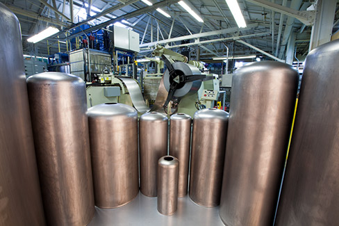 Since 1971, production of this cylinder has been consistent and substantial. A long-term business relationship resulted, and other-sized pressure cylinders were added to the mix.
During the mid-’90s, the customer’s marketing department became aware of several issues with the cylinder:
- The seams between the top and bottom halves and the foot stand allowed a crevice where rust could form, shortening the life of the product.
- The footstand was of a lighter gauge steel, which dented easily if dropped, compromising the stability of the cylinder.
- A cavity between the footstand and the bottom of the pressure cylinder could trap water, causing hidden rust problems and failure of the product.
- The cylinder was originally designed to meet the D.O.T. pressure certification that was lower than other certifications. Fire extinguisher testers and re-fillers had to acquire an additional license to service these cylinders, which affected the product’s appeal and limited marketing opportunities.
To increase the product’s marketability, the customer needed to:
- Upgrade the pressure rating to meet the requirements of Underwriter’s Laboratories.
- Keep the cylinder the same size as the existing product to ensure that existing hardware or installations would not have to be redesigned.
- Maintain the existing selling price.
The customer brought these needs to Larson Tool early in 1997 and asked for help in redesigning the existing product
3. The Concept
Back to Top
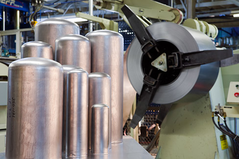 Larson determined that a one-piece cylinder design with a heavier wall thickness would solve the defined problems and meet the higher pressure rating required by U.L. The cost of the cylinder could not increase, despite added material cost due to heavier wall thickness. Direct labor costs would have to be reduced significantly. The manufacturing processes employed for this product had to be innovative and cost-effective, to make the cylinder economically viable.
The staff at Larson developed a set of design parameters to meet the customer’s requirements as well as the U.L. specifications. Drawings for the assembled cylinder, the component parts, and a bill of materials was submitted to the customer and approved.
One unresolved detail remained, however. The amount of draw reduction from blank to finished shell diameter exceeded the industry-accepted limits of drawability for cold-rolled steel. Among the key strengths of Larson Tool are innovations we have made in deep draw technology. Processes at the time “broke the rules,” but this draw had never been attempted. Some tangible evidence was needed before a large capital investment could be made.
Help was enlisted from an associate short-run metal stamper who had hydraulic draw press equipment suitable for the R&D work required. A scaled-down version of the shell was developed that proved the viability of the process. This success gave Larson the confidence needed to proceed with the project.
Temporary tooling was built and further development of the deep draw process was done. A set of prototype cylinders was produced and burst-tested. Results indicated that the cylinder design exceeded U.L. burst ratings by a good margin. Prototypes were delivered to the customer in the spring of 1998.
Specifications for a press line to produce the new shell were developed by Larson in the spring of 1998. Budgetary numbers and a timeline were presented to Larson management, who, in turn, informed the customer that the project was ready to proceed. In June 1998, the customer committed to the design of the new cylinder.
4. Execution
Back to Top
 Having extensive experience using hydraulic presses for draw work, the staff at Larson Tool selected a hydraulic press builder and began to work with them to design a custom-built press line suitable for fully automated transfer and operation.
Many innovative features were incorporated into the press line, including:
- Double-moving platens for blanking, hold-down, and drawing
- Ram-mounted punches guided through hold-down sleeve platens
- Multiple presses mounted on a common lower platen to facilitate automated transfer
- Servo-hydraulic draw height controls on the final draw operation
- A conveyorized aqueous spray wash in line with the presses
- Transfer automation integrated into the entire press and cleaning line
Design of tooling, transfer, presses, and wash line was done concurrently with CAD files shared between vendors and Larson on an ongoing basis.
The existing assembly line for the two-piece cylinder consisted of six separate operations, all done manually. The one-piece shell design would require only four operations. However, manually handling the additional weight of the shell was a concern from an ergonomic standpoint. Automating the assembly process addressed this concern, as well as reducing direct labor. Proposals for this equipment were solicited, and the contractor that offered a simple and efficient design for a custom-built assembly machine was selected.
Site work was completed and presses were installed in March 1999. Tooling, transfer automation, and washing equipment were installed, fine-tuned, and integrated using programmable controls. Start-up of production for the new cylinder was critical, since supply lines of raw material for the old design were replaced by the new material at the mill three months prior. There was no allowance for the overlap of old and new production.
Production on the old design shells ceased, and the new design was started in June of ’99—just 11 weeks from the arrival of presses. Assembly of cylinders was done manually at first, with automated equipment delivered and installed three weeks later. Deliveries to the customer were uninterrupted through the transition. More debugging by the Larson staff was required after the equipment went into production, but by July ’99 the labor reduction goals were realized.
5. Equipment Specification
Back to Top
 The complete production line consists of:
- 1 – Double-acting blank and draw press; 100 ton, 8” stroke lower platen, 100 ton, 32” stroke upper platen
- 1 – Double-acting redraw press; 75 ton, 36” stroke inner ram, 25 ton, 24” stroke outer platen; inner ram connected directly to tooling post, guided through bushing in outer platen
- 1 – Double-acting final draw press; 60 ton, 48” stroke inner ram, 25 ton, 30” stroke outer platen; inner ram connected directly to tooling post, guided through bushing in outer platen
- 1 – Single-acting pierce and extrude press; 20 tons capacity, 30” stroke
- Redraw, final draw, and pierce & extrude presses are mounted on a common lower platen to facilitate transfer automation
- 1 – Single-acting pinch trim press; 75 tons capacity, 24” stroke
- Servo-driven automated transfer between redraw, final draw, and extrude presses with a turn-over arm to place the shell on the wash line, and turn-over and linear motion to place the shell in pinch trim station
- Complete conveyorized aqueous spray wash line
- Related material handling equipment, including one 10,000# capacity pay-off reel with coil car and a Servo-driven feed/straightener with .120 x 30” capacity
An eight-station automated assembly machine with all components magazine-fed into assembly stations. A PLC-controlled dot matrix pin stamper serializes each assembly for lot control as it is assembled.
6. Functional Improvement of Design
Back to Top
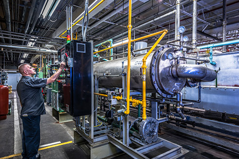 The new cylinder design addressed and solved the customer’s design issues, including:
- Elimination of seam between top and bottom shell halves, and the related rust problems.
- The pressed-in bottom closure and its brazed joint provide a double thickness of material at the bottom edge, which is much more dent-resistant than the old footstand design.
- Elimination of the footstand and the cavity within it, which caused water entrapment and rust problems.
The heavier-walled shell allows for higher test and burst pressures, and permits certification by U.L.
7. Cost-Savings and Productivity Gains
Back to Top
 As the changeover from old to new design cylinder took place, Larson’s customer increased its sales force to penetrate new markets. From the first day of production, greater demands than ever before were placed on the new line. Put to the test, gains were quickly realized:
- Daily volume increased by 33%.
- Productivity increased by more than 15%.
- The number of components in the cylinder assembly was reduced from seven to five, freeing up production equipment elsewhere in the factory.
- Costs were reduced by eliminating expensive paste-type brazing compounds and the high maintenance of related dispensing equipment.
- Direct labor was reduced by 35% between press line and assembly automation. Production personnel were made available for other areas in the factory.
- Profit margins on the new cylinder provided a budget for an expeditious payoff schedule on Larson’s capital investment.
Since requirements by U.L. for destructive testing are far less than for D.O.T. scrap, testing was reduced by more than 80%. Labor was reduced by eliminating a full-time lab position.
8. Conclusion
Back to Top
 This effort involved multiple departments and brought together the collective skills of many disciplines, drawing on Larson’s collective experience with deep-draw technology, automation, press work, and hydraulics. Since that initial effort, there has been continual improvement and refinement of the processes and technologies utilized in this initial effort—all resulting in a steady stream of cost-savings to our customers.
In addition, we have applied these processes and technologies to many other areas throughout our organization. The systemic impact has been positive—resulting in a vast number of improvements in efficiency and cost reductions that have benefited our entire customer base.
Larson continues to look beyond the obvious and explore deeper to provide our customers with custom solutions to problems and opportunities for growth.

